Chevrolet Sonic Repair Manual: Engine Coolant Thermostat Housing Replacement (LUW)
- Removal Procedure
-
- Remove the battery tray. Refer to Battery Tray Replacement.
- Raise and support the vehicle. Refer to Lifting and Jacking the Vehicle.
- Drain the cooling system. Refer to Cooling System Draining and Filling.
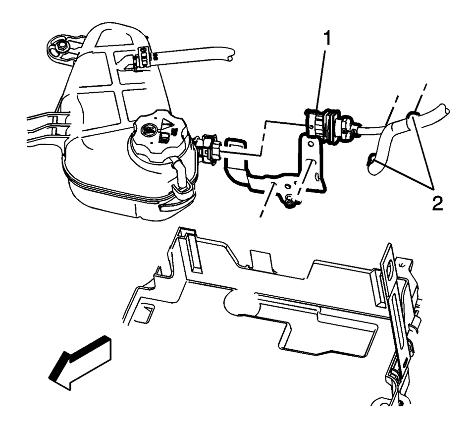
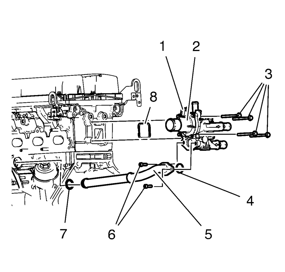
- Disconnect the engine harness connector (1) and harness fasteners (2) from the engine harness bracket, attached to the thermostat housing.
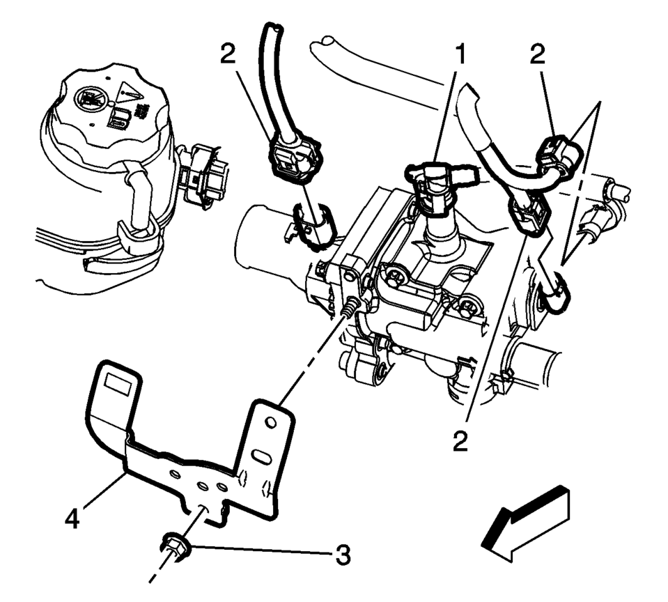
- Disconnect the throttle body heater inlet hose (1) and the electrical connectors (2) from the thermostat housing.
- Remove the engine harness bracket nut (3) and bracket (4) from the thermostat housing.
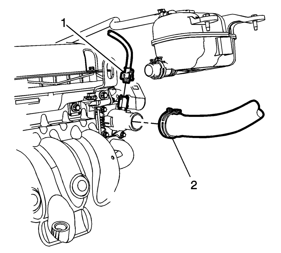
- Remove the radiator inlet hose (2) from the engine coolant thermostat housing.
- Remove the heater outlet hose from the engine coolant thermostat housing. Refer to Heater Outlet Hose Replacement.
- Remove the heater inlet hose from the engine coolant thermostat housing. Refer to Heater Inlet Hose Replacement.
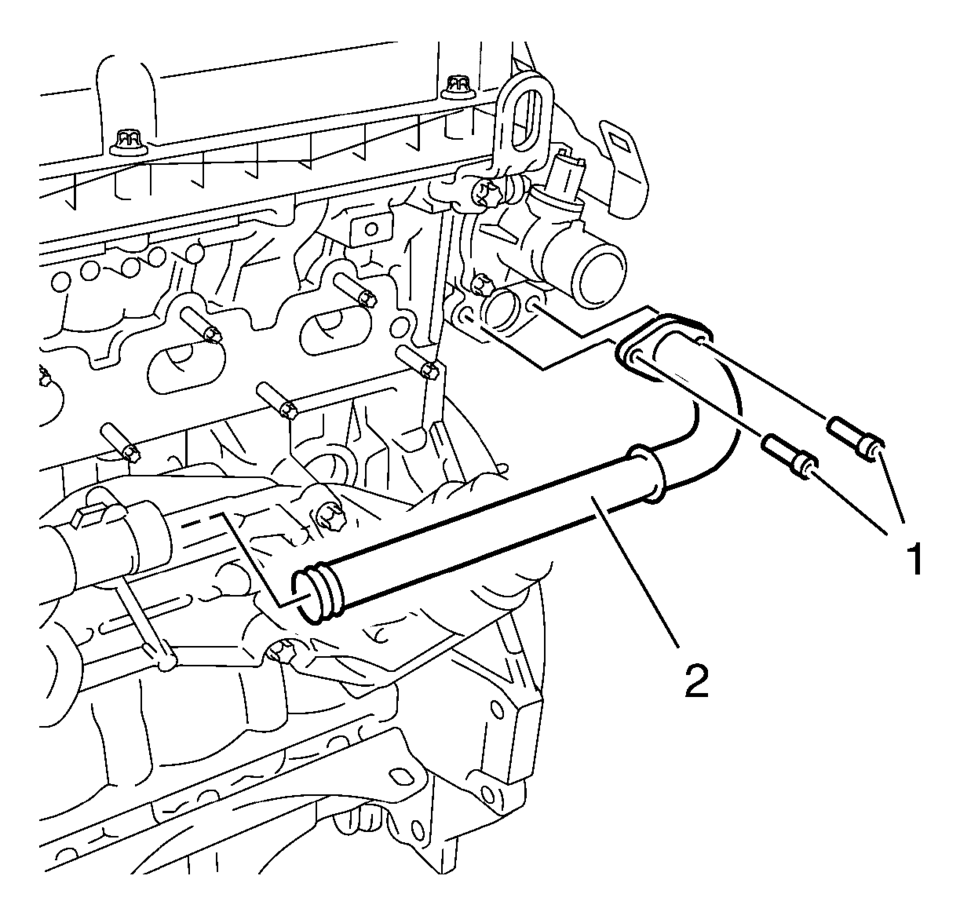
- Remove the engine oil cooler outlet pipe bolts (1).
- Remove the engine oil cooler outlet pipe (2) from the engine coolant thermostat housing.
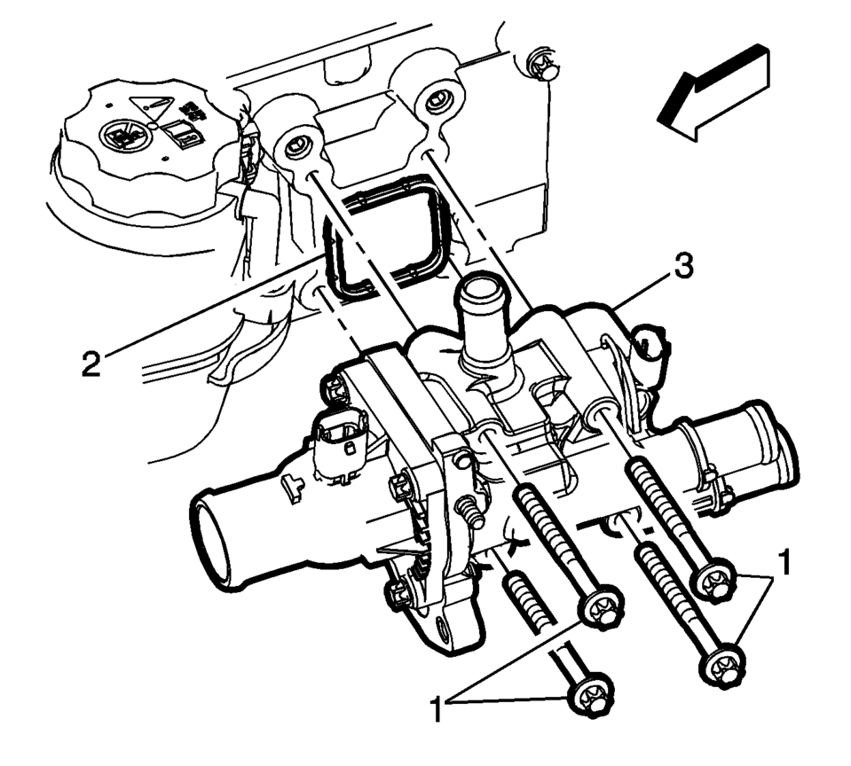
- Remove the engine coolant thermostat housing mounting bolts (1) and discard the seal (2).
- Remove the engine coolant thermostat housing (3) from the engine.
- Installation Procedure
-
- Clean the sealing surface.
- Install a NEW engine coolant thermostat housing seal (2).
- Loosely install the engine coolant thermostat housing mounting bolts (1).
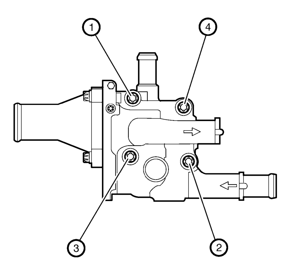
- Tighten the 4 engine coolant thermostat housing bolts to 8 Y (71 lb in)
in sequence (1?E?E?E).
- Install NEW engine oil cooler pipe seals (4, 7).
- Install the engine oil cooler pipe (5).
- Install the 2 engine oil cooler pipe bolts (6) and tighten to 8 Y
(71 lb in)
.
- Install the heater inlet hose to the engine coolant thermostat housing. Refer to Heater Inlet Hose Replacement.
- Install the heater outlet hose to the engine coolant thermostat housing. Refer to Heater Outlet Hose Replacement.
- Connect the electrical connectors (2) to the engine coolant thermostat housing.
- Install the throttle body heater inlet hose (1) to the engine coolant thermostat housing.
- Install the engine coolant thermostat housing bracket (4) and nut (3)
and tighten to 6 Y (53 lb in)
.
- Install the radiator inlet hose (2) to the engine coolant thermostat housing.
- Fill the cooling system. Refer to Cooling System Draining and Filling.
- Install the battery tray. Refer to Battery Tray Replacement.
- Start the engine and check for coolant leaks.
Caution:
Following the proper fastener tightening sequence and torque is essential. Failure to do so may fracture the thermostat housing.
Caution:
Refer to Fastener Caution.
Note:
Push the engine oil cooler pipe into the engine oil cooler.
 Engine Coolant Thermostat Housing Removal
Caution: Refer to Engine Coolant Thermostat Housing Caution.
Remove the engine coolant thermostat housing retainer nut (4).
Remove the engine coolant thermostat housing ...
 Engine Coolant Thermostat Installation
Caution: Refer to Engine Coolant Thermostat Housing Caution.
Clean the engine coolant sealing surfaces.
Install the engine coolant seal (1).
Install the engine coolant ...
Other materials:
Fog Lamps
For vehicles with front fog lamps, the button is on the outboard side of the
instrument panel.
The ignition must be on to turn on the fog lamps.
(Fog Lamps): Press to turn the
fog lamps on or off. An indicator light on the instrument cluster comes on when
the fog lamps are on.
The fog la ...
SIR Service Precautions
General Service Instructions
Warning: When performing service on or near the SIR components
or the SIR wiring, the SIR system must be disabled. Refer to SIR Disabling
and Enabling . Failure to observe the correct procedure could cause deployment
of the SIR components, person ...
Master Cylinder Replacement
Removal Procedure
Warning: Refer to Brake Fluid Irritant Warning.
Caution: Refer to Brake Fluid Effects on Paint and Electrical
Components Caution.
Place the ignition switch in the OFF position.
Remove the battery. Refer to Battery Replacement.
Disconnect ...

0.0084