Chevrolet Sonic Repair Manual: Engine Replacement (Automatic Transmission)
Special Tools
- J-45859 Wheel Drive Shaft Remover
- CH-807 Closure Plugs
For equivalent regional tools, refer to Special Tools.
- Removal Procedure
-
- Remove the battery and battery tray. Refer to Battery Tray Replacement.
- Relieve the fuel system pressure. Refer to Fuel Pressure Relief.
- Recover the refrigerant. Refer to Refrigerant Recovery and Recharging.
- Remove the front tire and wheel assembly. Refer to Tire and Wheel Removal and Installation.
- Remove the front bumper fascia. Refer to Front Bumper Fascia Replacement.
- Remove the front wheelhouse liner inner front extensions. Refer to Front Wheelhouse Liner Inner Front Extension Replacement.
- Drain the cooling system. Refer to Cooling System Draining and Filling.
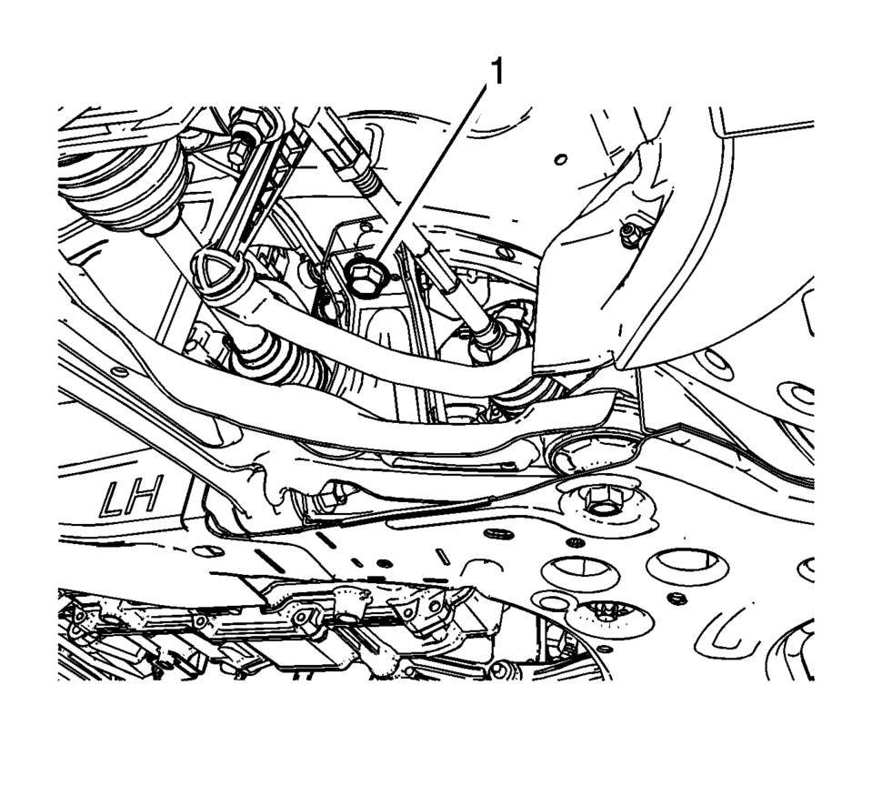
- Remove the lower intermediate steering shaft bolt (1) and slide the shaft away from steering column. Refer to Intermediate Steering Shaft Replacement.
- Remove the air cleaner assembly (1). Refer to Air Cleaner Assembly Replacement.
- Remove the junction block cover (1).
- Remove the positive battery cable nut (1) from the junction block.
- Remove the positive battery cable (2) from the junction block.
- Remove the positive cable nut (1) and battery positive cable, from the battery positive cable junction block.
- Disconnect the body wiring master harness connector (2), from the battery positive cable junction block.
- Remove the junction block nut (1).
- Remove the junction block bolts (2).
- Disconnect the wiring harness from the junction block base.
- Remove the junction block (3) from the base.
- Disconnect the wiring harness plug from the front compartment fuse block.
- Reposition the wiring harness (1) on top of the engine.
- Remove the ground nuts (1) and reposition the wiring harness (2) aside.
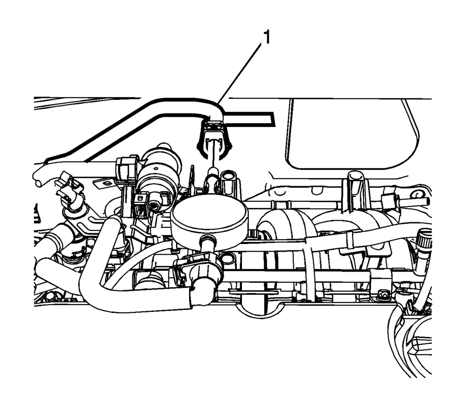
- If equipped with electrical vacuum pump, disconnect the electrical connector and remove the brake booster hose (1).
- Disconnect the heater inlet hose (1) from the heater core. Refer to Heater Inlet Hose Replacement.
- Disconnect the heater outlet hose (1) from the heater core. Refer to Heater Outlet Hose Replacement.
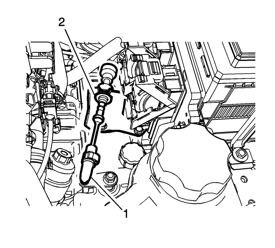
- Disconnect the transmission range selector lever cable terminal (1) from the transmission manual shift lever pin.
- Remove the transmission range selector lever cable (2) from the cable bracket.
- Remove the radiator surge tank (1) and position aside. Refer to Radiator Surge Tank Replacement.
- Disconnect the fan connector.
- Remove air conditioning compressor and condenser hose nut (1).
- Remove air conditioning compressor and condenser hose (2) from refrigerant hose.
- Disconnect the fuel feed pipe (1). Refer to Plastic Collar Quick Connect Fitting Service.
- Install and close the fuel feed pipe with CH-807 plug.
- Disconnect the engine coolant sensor from radiator.
- Insert a brass drift or punch (1) in the cooling fins of the front brake rotor (2).
- Rotate the brake rotor until it comes in contact with the brake caliper mount bracket (5).
- Use a suitable tool to release the crimping on the wheel drive shaft retaining nut.
- The wheel drive shaft retaining nut (1) must be discarded after removal.
- Remove and discard the wheel drive shaft nut (1).
- Remove the upper stabilizer shaft link nut (1).
- Disconnect the stabilizer shaft link (2).
- Remove and DISCARD the steering linkage outer tie rod nut (1).
- Separate the steering linkage outer tie rod (2) from the steering knuckle. Steering Linkage Outer Tie Rod Replacement.
- Separate the control arm ball joint from the steering knuckle. Refer to Lower Control Arm Replacement.
- Using the J-45859 wheel drive shaft remover (2), separate the wheel drive shaft from the steering knuckle (1).
- Remove the upper stabilizer shaft link from the absorber on both sides. Refer to Stabilizer Shaft Link Replacement.
- Remove the front exhaust pipe. Refer to Exhaust Front Pipe Replacement.
- Remove the lower oil pan to transmission lower bolts (1).
- Remove the lower oil pan to transmission lower bolts (1) and nut (2).
- Remove the frame braces.
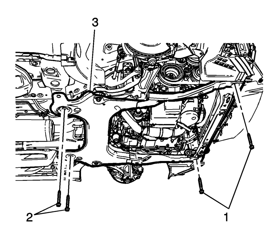
- Remove the frame front bolts (1).
- Position an engine support table under the powertrain assembly.
- Remove the upper frame suspension retaining bolts (1) on both sides.
- Mark the location of the right engine mount bolts (1) before removing.
- Remove and Discard the right side engine mount bolts (1). Refer to Engine Mount Replacement.
- Mark the location of the transmission mount bolts (1) before removing.
- Remove and DISCARD the transmission mount bolts (1) ?left side. Refer to Transmission Mount Replacement - Left Side.
- Disconnect any additional electrical connections as necessary.
- Raise the vehicle until the powertrain is clear for removal.
- Remove the starter. Refer to Starter Replacement.
- Remove the torque converter bolt access plug next to the starter opening.
- Remove the torque converter bolts.
- Remove the upper transmission to engine bolts (1) and separate the engine and transmission.
- Disconnect any electrical connectors as needed.
- Install the engine to the engine stand.
- Transfer parts as needed.


.-

Note:
Perform steps 33 through 41 to both sides.

Note:


Note:
Reverse the wheel lug nuts and washers so the flat part of the wheel nut is facing the washers.


Note:
Blocks of wood can be used between the front of the frame and the oil pan to table in order to level the powertrain during the removal.


- Installation Procedure
-
- Remove the engine from the engine stand.
- Install the transmission to the engine.
- Install the upper transmission to engine bolts (1)
and tighten to 60 Y (44 lb ft)
.
- Place the powertrain into the front frame.
- Slowly lower the body onto the powertrain.
- Install the NEW left transmission mount to transmission
bolts (1) and tighten to 50 Y (37 lb ft)
plus 70 degrees
.
- Install the NEW right side engine mount bolts (1)
and tighten to 50 Y (37 lb ft) plus 70 degrees
.
- Perform Powertrain Mount Balancing.
- Align the frame and body through alignment hole (1).
- Install the frame (3) rear bolts (2) and tighten to 135 Y
(100 lb ft)
.
- Install the frame (3) front bolts (1) and tighten to 58 Y
(43 lb ft)
.
- Install the upper frame suspension retaining bolts (1) on both sides
and tighten to 135 Y (100 lb ft)
.
- Remove the lift table.
- Install the lower oil pan to transmission bolts (1) and tighten to
40 Y (30 lb ft)
.
- Install the lower oil pan to transmission lower bolts (1) and tighten
to 60 Y (44 lb ft)
.
- Install the lower oil pan to transmission lower and nut (2) and tighten
to 40 Y (30 lb ft)
.
- Install NEW flex plate to torque converter bolts and tighten to 60 Y
(44 lb ft)
.
- Install the starter. Refer to Starter Replacement.
- Install the front exhaust pipe. Refer to Exhaust Front Pipe Replacement.
- Inset the wheel drive shaft to the steering knuckle.
- Install the NEW steering linkage outer tie rod nut (1) and tighten to
30 Y (22 lb ft) Plus 128 degrees
.
- Install the steering linkage outer tie rod to the steering knuckle. Refer to Steering Linkage Outer Tie Rod Replacement.
- Install the control arm ball joint to the steering knuckle. Refer to Lower Control Arm Replacement.
- Connect the stabilizer shaft link (2).
- Install the upper stabilizer shaft link nut (1) and tighten to 65 Y
(48 lb ft)
.
- Insert a brass drift or punch (1) in the cooling fins of the front brake rotor (2).
- Rotate the brake rotor until it comes in contact with the brake caliper mount bracket (5).
- Install the NEW wheel drive shaft nut (1) and tighten to 250 Y
(184 lb ft)
.
- Using a punch (1), stake the wheel drive shaft nut.
- Remove the CH-807 plug.
- Connect the fuel feed pipe (1). Refer to Plastic Collar Quick Connect Fitting Service.
- Connect the engine coolant sensor from radiator.
- Install air conditioning compressor and condenser hose to the refrigerant hose.
- Install air conditioning compressor and condenser hose nut (1) tighten
nut to 22 Y (16 lb ft)
.
- Install the radiator surge tank (1). Refer to Radiator Surge Tank Replacement.
- Connect the fan connector.
- Install the transmission range selector lever cable (2) to the cable bracket.
- Connect the transmission range selector lever cable terminal (1) to the transmission manual shift lever pin.
- Adjust the automatic transmission range selector lever cable. Refer to Range Selector Lever Cable Adjustment.
- Connect the heater inlet hose to the heater core (1). Refer to Heater Inlet Hose Replacement.
- Connect the heater outlet hose to the heater core (1). Refer to Heater Outlet Hose Replacement.
- If equipped with electrical vacuum pump, connect the electrical connector and install the brake booster hose (1).
- Install the ground nuts (1) and reposition the wiring harness (2).
- Clip in the wiring harness plugs (1).
- Install the junction block to the base.
- Install the junction block bolts (2) and tighten to 5 Y
(44 lb in)
.
- Install the junction block nut (1) and tighten to 5 Y
(44 lb in)
.
- Install the battery positive cable to the battery positive cable junction
block and tighten nut (1) to 5 Y (44 lb in)
.
- Connect the body wiring master harness connector (2), to the battery positive cable junction block.
- Position the positive battery cable to the junction block.
- Install the positive battery cable nut (2) and tighten to 7 Y
(62 lb in)
.
- Install the junction block cover (1).
- Install the air cleaner assembly (1). Refer to Air Cleaner Assembly Replacement.
- Install the lower intermediate steering shaft bolt (1). Refer to Intermediate Steering Shaft Replacement.
- Install the battery and battery tray. Refer to Battery Tray Replacement.
- Install the front tire and wheel assembly. Refer to Tire and Wheel Removal and Installation.
- Install the front bumper fascia. Refer to Front Bumper Fascia Replacement.
- Install the front wheelhouse liner inner front extensions. Refer to Front Wheelhouse Liner Inner Front Extension Replacement.
- Evacuate and charge the refrigerant system. Refer to Refrigerant Recovery and Recharging.
- Fill the cooling system. Refer to Cooling System Draining and Filling.
Caution:
Refer to Fastener Caution.
Caution:
Refer to Torque-to-Yield Fastener Caution.
Caution:
Refer to Torque-to-Yield Fastener Caution.

Note:
Perform steps 20 through 29 to both sides.
Caution:
Refer to Torque-to-Yield Fastener Caution.


.-
 Electronic Component Description
Control Solenoid Valve Assembly
(1)
Pressure Control Solenoid 3 (R-1/4-5-6)
(2)
(GEN 1) Pressure Control Solenoid 2 (3-5-R) ...
 Fluid Passages (Gen 1)
Figure 1:
Case - Control Valve Body Side (Left)
Figure 2:
Case - Pump Side (Back)
Figure 3:
Control Valve Body - Case Side (Left)
Figure 4:
Control ...
Other materials:
Antilock Brake System (ABS)
This vehicle has ABS, an advanced electronic braking system that helps prevent
a braking skid.
When the vehicle begins to drive away, ABS checks itself.
A momentary motor or clicking noise might be heard while this test is going on,
and it might even be noticed that the brake pedal moves a lit ...
Cargo Center Courtesy Lamp Bulb Replacement (Hatchback)
Cargo Center Courtesy Lamp Bulb Replacement
Callout
Component Name
1
Rear Compartment Courtesy Lamp
Refer to Rear Compartment Courtesy Lamp Replacement
2
Cargo Lamp Bulb
...
Engine Component Description
Cylinder Block
The cylinder hollow frame structured in–line 4 cylinder. The block has 5 crankshaft
bearings with the thrust bearing located on the third bearing from the front
of the engine.
Crankshaft
The crankshaft is a steel crankshaft. It is supported ...

0.0109