Chevrolet Sonic Repair Manual: Intake Manifold Replacement (LUW)
- Removal Procedure
-
- Disconnect the negative battery cable. Refer to Battery Negative Cable Disconnection and Connection.
- Remove the throttle body assembly. Refer to Throttle Body Assembly Replacement.
- Disconnect wiring harness plug.
- Disconnect the pipes from the evaporative emission canister purge solenoid valve (1).
- Remove the evaporative emission canister purge solenoid valve (1) and the rubber mounting from the intake manifold (2).
- Disconnect and reposition the electrical connectors as necessary.
- Remove the fuel injector rail. Refer to Fuel Injector Replacement.
- Remove the manifold absolute pressure sensor. Refer to Manifold Absolute Pressure Sensor Replacement.
- Disconnect the booster vacuum pipe (1) from the intake manifold.
- Remove the front wheel drive shaft right side. Refer to Front Wheel Drive Shaft Replacement.
- Remove the starter. Refer to Starter Replacement.
- Remove the generator. Refer to Generator Replacement.
- Remove the front exhaust pipe. Refer to Exhaust Front Pipe Replacement.
- Remove and DISCARD the transmission rear mount to bracket through bolt (1).
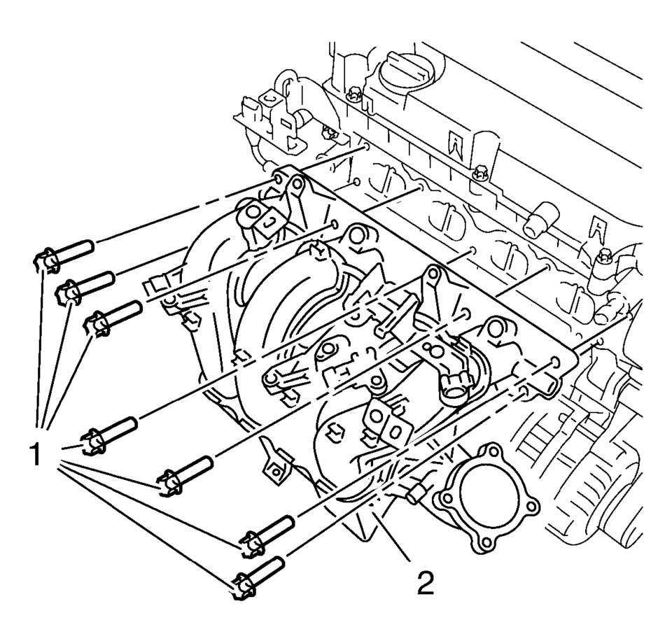
- Remove the intake manifold bolts (1).
- Remove the intake manifold (2).
- Clean and inspect the intake manifold. Refer to Intake Manifold Cleaning and Inspection.


- Installation Procedure
-
- Clean the sealing surfaces.
- Install the NEW gasket.
- Install the intake manifold (2) and the 7 intake manifold bolts (1)
and tighten to 20 Y (15 lb ft)
.
- Install the NEW transmission rear mount to bracket through bolt (1)
and tighten to 80 Y (59 lb ft) plus 45-60 degrees
.
- Install the generator. Refer to Generator Replacement.
- Install the starter. Refer to Starter Replacement.
- Install the front exhaust pipe. Refer to Exhaust Front Pipe Replacement.
- Install the front wheel drive shaft right side. Refer to Front Wheel Drive Shaft Replacement.
- Connect the booster vacuum pipe (1) to the intake manifold.
- Install the manifold absolute pressure sensor. Refer to Manifold Absolute Pressure Sensor Replacement.
- Connect the electrical connectors as necessary.
- Install the fuel injector rail. Refer to Fuel Injector Replacement.
- Install the evaporative emission canister purge solenoid valve (1) and the rubber mounting to the intake manifold (2).
- Connect the pipes to the evaporative emission canister purge solenoid valve (1).
- Connect wiring harness as necessary.
- Install the throttle body assembly. Refer to Throttle Body Assembly Replacement.
- Connect the negative battery cable. Refer to Battery Negative Cable Disconnection and Connection.
Caution:
Refer to Fastener Caution.
 Intake Manifold Replacement (LDE)
Removal Procedure
Disconnect the negative battery cable. Refer to Battery Negative Cable
Disconnection and Connection.
Remove the throttle body assembly. Refer to Throttle Body As ...
 Intake Manifold Tuning Valve Actuator Replacement
Intake Manifold Tuning Valve Actuator Replacement
Callout
Component Name
Preliminary Procedure
Properly raise and support the v ...
Other materials:
Instrument Panel Compartment Door Dampener Replacement
Instrument Panel Compartment Door Dampener Replacement
Callout
Component Name
Preliminary Procedure
Remove the instrument panel lower compartment. Refer to Instrument Panel
Lower Compartment Replacement.
1 ...
Fastener Tightening Specifications - Wheels
Fastener Tightening Specifications
Application
Specification
Metric
English
Clamp Fit TPM Stem Locknut
7 Y Dynamically
62 lb in
Clamp ...
Front Wheel Drive Shaft Seal Replacement - Case Side
Front Wheel Drive Shaft Seal Replacement - Case Side
Callout
Component Name
1
Front Wheel Drive Shaft Oil Seal
Special Tools
DT-23129 Universal Seal Remover
DT-47790 Seal Installer
GE-6125-1B Slide Hamme ...

0.0068