Chevrolet Sonic Repair Manual: Manual Shift Detent Lever with Shaft Position Switch Assembly Replacement
Special Tools
- DT-41229 Manual Shaft Pin Installer
- DT-48550 Detent Lever Pin Remover
For equivalent regional tools, refer to Special Tools.
- Removal Procedure
-
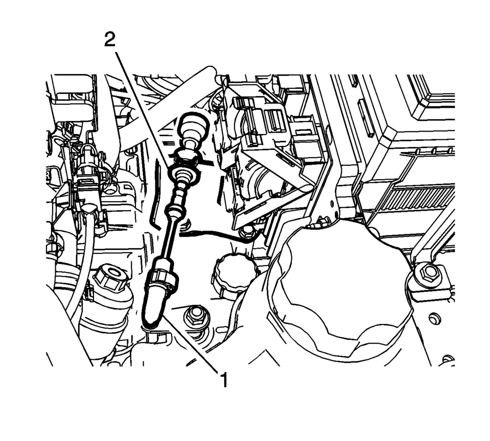
- Disconnect the transmission range selector lever cable terminal (1) from the transmission manual shift lever pin.
- Remove the control valve body cover. Refer to Control Valve Body Cover Replacement.
- Remove the control valve body. Refer to Control Valve Body Replacement.
- Remove the manual shaft detent lever hub pin (1) using DT-48550 remover.
- Remove the manual shift shaft pin (5) using diagonal pliers or equivalent tool. Discard the pin.
- Remove the manual shaft (2).
- Disconnect the actuator rod (3) from the detent lever assembly. Do not remove the actuator rod from the transmission case.
- Do not pull the park actuator rod end out beyond the machined oil passage surface in the case. A no park condition will exist if the park pawl actuator assembly is pulled out of the transmission too far and the actuator rod disengages from the park pawl. The transmission assembly will require disassembly to reinstall the actuator rod over the park pawl.
- Remove the manual shaft detent (w/shift position switch) lever assembly (4).

Note:
- Installation Procedure
-
- Install the manual shaft detent (w/shift position switch) lever assembly (4).
- Install the manual shaft (2).
- Install the manual shaft detent lever hub pin (1)
using DT-41229 Installer.
Specification
Install the Manual Shaft Detent Lever Hub Pin to height of (b) 7.9 mm (0.38 in). - Install the NEW manual shift shaft pin (5) using
DT-41229 Installer. Use a NEW pin to ensure proper engagement with
the case.
Specification
Inspect pin installed height is within (a) 7.2?.2 mm (0.28?.32 in). - Install the control valve body. Refer to Control Valve Body Replacement.
- Install the control valve body cover. Refer to Control Valve Body Cover Replacement.
- Connect the transmission range selector lever cable terminal (1) from the transmission manual shift lever pin.

Note:
Connect the actuator rod (3) to the detent lever assembly.
Note:
Lubricate the shaft with automatic transmission fluid to prevent damage to the manual shift shaft seal during installation.
Caution:
Use the manual shaft pin installer to install the pin at the correct height in order to properly secure the manual shaft. If you install the pin too deep, the case bore may crack.
 Lift Plate and Holding Fixture Removal
Lift Plate and Holding Fixture Removal
Callout
Component Name
1
DT-46625 Transmission Holding Fixture
For equivalent ...
 Manual Shift Detent Lever with Shaft Position Switch Assembly and Park Pawl
Actuator Installation
Manual Shift Detent Lever with Shaft Position Switch Assembly and Park Pawl
Actuator Installation
Table 1:
Park Pawl Actuator Guide Installation
Table 2:
Park Pawl Actuator Installation
Park Pawl Actuator Guide Installation
Park Pawl Actuator Guide I ...
Other materials:
Front Side Door Window Rear Guide Replacement
Front Side Door Window Rear Guide Replacement
Callout
Component Name
Preliminary Procedure
Remove the front side door trim panel. Refer to Front Side Door Trim
Replacement.
1
Front Side Door Win ...
Air Conditioning Compressor Oil Balancing
Draining Procedure
Note: Drain and measure as much of the refrigerant oil as
possible from the removed compressor.
Drain the oil from both the suction and discharge ports of the removed
compressor into a clean, graduated container. Rotate the compressor sha ...
Fuel Tank Pressure Sensor Replacement
Fuel Tank Pressure Sensor Replacement
Callout
Component Name
Preliminary Procedure
Remove the fuel tank. Refer to Fuel Tank
Replacement.
1
Fuel Tank Pressure Sensor
Procedure
Disco ...

0.0082