Chevrolet Sonic Repair Manual: Transmission Assemble (Gen 2)
Special Tools
- 3-9506289 Universal Adapter
- R-0007758 Holding Fixture
- S-9407197 Differential Rotating Tool
- S-9407198 Differential Bearing Race Wrench
For equivalent regional tools, refer to Special Tools.
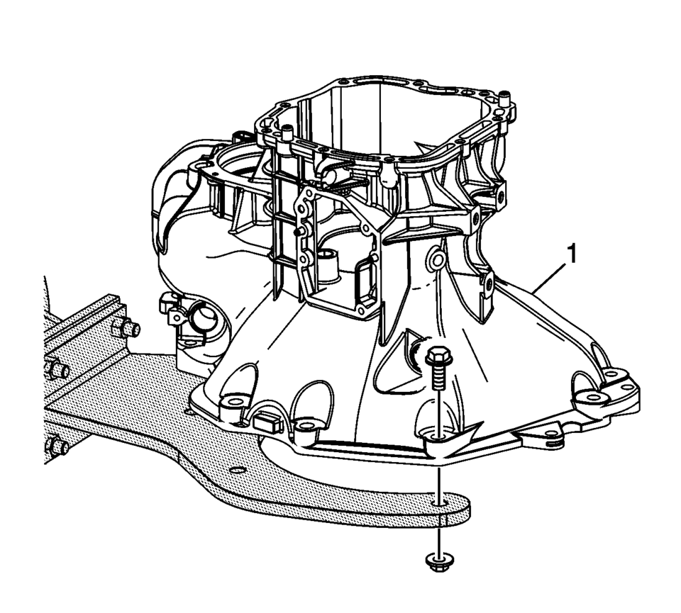
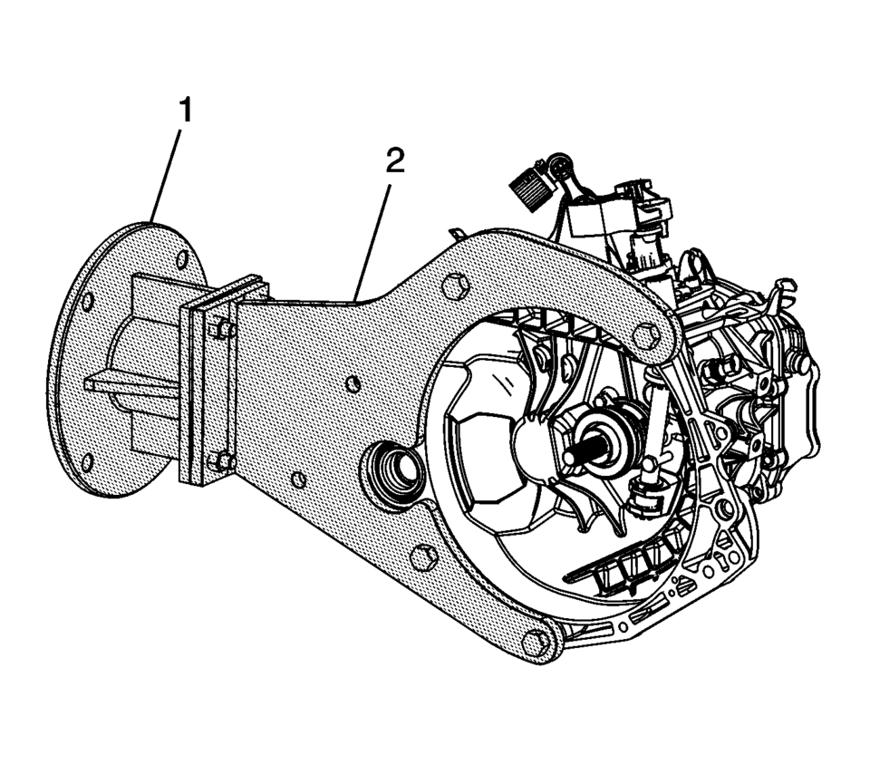
- Install the clutch and differential housing assembly (1) onto the R-0007758 holding fixture.
- Install the front differential carrier (1).
- Install the gasket (3) and differential carrier cover (2).
- Install the front differential carrier cover bolts (1).
Tighten to 7 Y (61.96 lb in)
.
- Lubricate the O-ring seal (2) with multipurpose grease and install onto the differential bearing adjuster (1).
- Lubricate the threads on the differential bearing adjuster with multipurpose grease.
- Using S-9407198 differential bearing race wrench install the front differential bearing adjuster (1).
- Align marks on the differential bearing adjuster and case (1).
- Using the S-9407197 differential rotating tool and a torque wrench, rotate the differential (1) 1 revolution per second.
- The breakaway bearing torque should be:


Note:
If all the components are re-used align adjuster to marks. If any component was replaced go to the next step.

Note:
If no components were replaced, the bearing adjuster can be aligned to the marks. If any component was replaced, the following procedure must be performed.
- Re-use bearing ?#8201;60?00 Ncm
- New Bearing ?#8201;150?10 Ncm

.

.

Note:
The reverse gear shaft snap ring (6) MUST be installed even if not originally equipped to prevent shifting issues caused by incorrect assembly or parts not in position.
.

.
.


.

.
 Transmission Assemble (Gen 1)
Special Tools
3-9506289 Universal Adapter
R-0007758 Holding Fixture
S-9407197 Differential Rotating Tool
S-9407198 Differential Bearing Race Wrench
For equivalent regional tools, refer ...
 Transmission Component and System Description
The mechanical components of the 6T30/40/45/50 are as follows:
A torque converter with an electronically controlled capacity clutch (ECCC)
Gear-type fluid pump assembly
1??? and low ...
Other materials:
Inspection/Maintenance Complete System Set Procedure
Diagnostic Instructions
Perform the Diagnostic System Check - Vehicle
prior to using this diagnostic procedure.
Review Strategy Based Diagnosis for an
overview of the diagnostic approach.
Diagnostic Procedure Instructions provides
an overview of each diagnostic cat ...
Automatic Transmission Shift Lock Control Description and Operation
The automatic transmission park lock control system is a safety device that prevents
an inadvertent shift out of PARK. The driver must press the brake pedal before moving
the park lever out of the PARK position. The system consists of the following components:
The automatic transmission pa ...
Fluid Passages (Gen 1)
Figure 1:
Case - Control Valve Body Side (Left)
Figure 2:
Case - Pump Side (Back)
Figure 3:
Control Valve Body - Case Side (Left)
Figure 4:
Control Valve Body - Channel Plate Side (Right
- No Valves)
Figure 5:
Pump Body - Pump Cove ...

0.0066