Chevrolet Sonic Repair Manual: Engine Oil Cooler Inlet Pipe Replacement (LUW)
- Removal Procedure
-
- Drain the cooling system. Refer to Cooling System Draining and Filling.
- Remove the exhaust manifold with catalytic converter. Refer to Exhaust Manifold with Catalytic Converter Replacement.
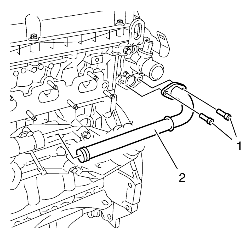
- Remove the engine oil cooler pipe bolts (1) and the engine oil cooler pipe (2).
- Remove the engine oil cooler outlet pipe bolts (1) and the engine oil cooler outlet pipe bracket (2).
- Remove the engine oil cooler assembly bolts (1) and remove the cooler (2).
- Remove the engine oil cooler inlet pipe (4) and seals (3).


- Installation Procedure
-
- Replace the seals on the engine oil cooler outlet pipe and the engine oil cooler pipe.
- Install the engine oil cooler inlet pipe (4) with NEW seals (3) to the engine oil cooler assembly.
- Position the engine oil cooler assembly (2) to the engine block.
- Install the engine oil cooler assembly bolts (1) and tighten to 25 Y
(19 lb ft)
.
- Install the engine oil cooler outlet pipe mounting bolts (1) and the
bracket (2) to the water pump housing and tighten to 8 Y (71 lb in)
.
- Install the engine oil cooler pipe (3) to the thermostat housing and
tighten bolts (1) to 8 Y (71 lb in)
.
- Install the exhaust manifold with catalytic converter. Refer to Exhaust Manifold with Catalytic Converter Replacement.
- Fill the cooling system. Refer to Cooling System Draining and Filling.
- Start the engine and check for coolant leaks.

Caution:
Refer to Fastener Caution.


 Engine Oil Cooler Housing Replacement
Removal Procedure
Drain the engine coolant. Refer to Cooling System Draining and Filling.
Drain the engine oil. Refer to Engine Oil and Oil Filter Replacement.
R ...
 Engine Oil Cooler Installation
Note: Lubricate the oil cooler seal (8) with clean engine oil.
Install the engine oil cooler assembly (6) along with 2 NEW sealings (8)
and (9). ...
Other materials:
OnStar Description and Operation
This OnStar® system consists of the following components:
Telematics communication interface control module
OnStar® three button assembly
Microphone
Cellular antenna
Navigation antenna
Bluetooth® antenna (If equipped)
Back up battery (If equipped)
This system also interfaces wi ...
Warm Up Three-Way Catalytic Converter Replacement (LUV,LUW)
Warm Up Three-Way Catalytic Converter Replacement
Callout
Component Name
Warning: Refer to Exhaust Service Warning.
Warning: Refer to Safety Glasses Warning.
Preliminary Procedure
Raise and support the ...
Drive Range, First Gear (Gen 1)
As the vehicle speed increases, the transmission control module (TCM) receives
input signals from the automatic transmission input and output speed sensors, throttle
position sensor and other vehicle sensors to determine the precise moment to deenergize
or ?urn OFF?the shift solenoid, and to c ...
0.0066
